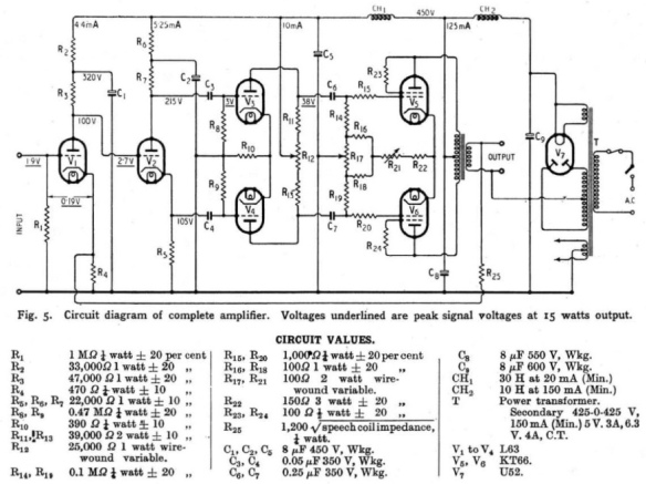
Above is the Williamson amplifier schematic. Thanks to Preservation Sound for everything they do and are, as they are the ones I took the above image from. Love the PS crew. If you need more information about amps or you want to see what other DIY-ers are doing, it’s a kick ass resource. The image is the original Williamson amp, which I believe he had a patent for in the ’40s. This is not a blog post about the history of these amps, as there are a nearly limitless number of variants and differentiations between manufacturers and years, and a bottomless amount of information about their history. This post is related to my recently constructed Satoru Kobayashi Marantz 8B.
When I was building the 8B I made, following (loosely) the instructions from MJ Magazine by Satoru Kobayashi from the year 2000, I lacked some parts during the initial construction stage. But I wanted to hear the amp now, not to wait for my parts. So naturally, I just shoved what I had in the chassis to see what the R-cores sounded like. I replaced the input tube, directly coupled to the phase inverters, with an input coupled to the phase inverters through a transformer and cap, driving from the triodes’ cathodes to the grids of the 6CG7s. It was super quiet, but sounded divine. At the time I also had a CCS on the phase inverter cathodes because I was waiting on my 13kΩ resistors from Mouser.
After I got my parts, I’d already made holes in the chassis for the transformers from Edcor USA. D’oh! Oh well. I guess I just have to include input transformers in my Marantz clone. The original didn’t have input transformers, and in order to preserve the topology of the original, I’ll have to do something I don’t like: using a transformer that can totally give a differential signal as a single ended device in favor of still letting the phase splitters do their job. I prefer to allow the iron and copper to do the splitting of phase in every other design I’ve ever done. In this case, since I am attempting a modernized clone of something ancient, I’m attempting to do as little changing of the circuit as possible. Here in the States, the designs using tubes as phase splitters were common; in Europe, however, it was far more common to see transformers doing the splitting of phase. I prefer the European design aesthetic.
I then ran into a problem: my usual 600Ω:10kΩ input transformers were introducing a ton of noise into the circuit. I found this quite confounding. The noise seemed to be a loudly audible 60hz hum, with a splash of “zzzz” through the tweeters, suggesting a ground loop, toroidal transformer noise picked up through capacitive coupling of wires inside the chassis, or maybe a bad component. The low hum is the 60Hz fundamental wave, and the “zzz” from the tweeters is the capacitively coupled harmonics from the 60Hz fundamental. I spent an inordinate amount of time on this issue. I also noticed that there were high frequency oscillations on my oscilloscope, at about 880 kHz, but only on one channel. I was heartbroken. Why would there be so much fucking noise? Why would the introduction of a low to high impedance transformer cause a problem with the input circuitry? Transformers, in my limited experience, make all tube circuits better. The only exception I’ve heard would be the Berning ZOTL architecture, but that’s pretty advanced shit, and simply not possible for the DIY-er. So if transformers always help, let’s examine why this 600Ω:10kΩ is causing problems.
My toroidal transformers inside the Marantz are both not covered, so their magnetic fields are uncontained within the chassis. I’ve seen many many builds like this where the toroids are unshielded inside of the chassis, like Croft Instruments racks tend to be. My first thought was that it was possible that I had fucked up in the way I routed the rat’s nest of wiring inside the chassis. I’m pretty conscious about wiring, but in most cases in the past, the wiring hasn’t been too critical as there hasn’t been much power present in my older designs. The more current traveling through a wire, the more it’s field(s) will interact with the wires and fields around it. I figured at first that I needed to shield the transformers inside the chassis, so the input circuitry doesn’t get bathed in 60Hz field hum. I took Pendaflex (used for filing folder paper) and cut a couple of 3in tall strips, and lined them with 3M 1245-type embossed 1-oz copper adhesive strips. I wrapped them around the two transformers, and tried again. No significant difference.
My next thought was that I needed to shield the wires going from the input jack to the input transformers, and again from the transformers to the first tube socket. So I cut a bunch of my Mogami shielded interconnect wire, and soldered it into the input circuit. Again, essentially no difference. How could it be that I’ve shielded the wires, the power transformers, and re-routed everything carefully, and I’m still hearing the damn 60Hz hum? I thought for a few hours. OK. I need to shield the input transformers! So I dissected the amp again, disconnected and unbolted the input transformers, and shielded them with the 3M 1245 tape.
Before:

After:

I then soldered everything back into place, and tried again. Fuck! No significant change. What now? Having nicely shielded my input transformers, power transformers, and wire, I tried something: removing the transformers from the circuit. Bingo. The signal path noise was still present, but at a much much lower volume than before. And it’s listenable (the noise doesn’t cut through the mix.) I still need to do fine tuning for my noise floor related stuff, but clearly omitting the transformer was a good move. But why?
The Williamson amplifier has a ton of gain on the front end. In the ’40s and ’50s signals weren’t as “hot” as they are today, meaning that most amps from the distant past were designed with far more input gain than would be necessary today. The Williamson has a high gain pentode (or triode) tied to the phase splitters, all of which are high impedance and whose sensitivity easily can introduce noise into the circuit. The problem with the transformer isn’t that it picks up ambient field noise, the problem is that with a 1:4 step up going to the high gain input stage, the input circuit has too much gain, and the “noise” I’m hearing is the amplified noise floor. I believe that by replacing the 1:4 600Ω:10kΩ transformer with a 1:1 600Ω:600Ω transformer, that the input transformer’s benefits of isolation could be used in the Marantz 8B input stage without introducing too much noise into the circuit. I’ll be ordering a set this week. We’ll see if my theory is correct when they arrive.
